Project Overview
UWaterloo Rocketry Design Team
Eager to build and develop skills, I decided to take on some design teams. I have always been passionate about aerospace and aircraft, so Rocketry seemed to be the perfect fit for me
After joining, I chose to work on the structural sub-team. There, I was tasked to redesign a launch base from scratch with 4 key criteria in mind:
1. Light Weight
2. Manufacturability/Portability
3. Cost effectiveness
4. Elevation off the ground

How Does the Base Work Now?

1
The launch tower mechanism consists of two plates stacked on top of each other, connected by a hinge. The triangle truss that is used as a rail for the rocket is fastened to the top plate, allowing it to go from horizontal to vertical for transportation reasons.
2
A winch is connected to the top plate allowing the top plate to go from horizontal, to facing the sky once the rocket has been slotted onto the triangle truss horizontally. A small block is placed in between the to and bottom plate to achieve a 6 degree angle so the rocket is launched away from spectators
3
Finally, once the rocket and truss are vertical, the truss is held in place by guy wires applying equal tension on all sides of the tower.
Process
Drawings/Drafting
Firstly, I drafted up two separate ideas which met every criteria that was given to me for the launch tower base. Idea 1 was a octagonal shaped platform with adjustable pegs for uneven terrain. Two halves of the octagon would be attached to each other by a hinge for portability. The second design features a square baseplate divided into four smaller squares that are held together with pins/bolts for portability. It also features a "pin and slot" mechanism, similar to gym equipment, allowing for adjustable heights of specific legs. Both designs would be made of aluminum or brass which are both cheap, corrosion resistant materials.
In the end idea two was pursued, with some adjustments. These adjustments included: Triangle truss legs for strength, and spiked platforms at the base of each leg for stability. It was decided that the same tower lifting mechanism would be used, and integrated into my new tower base design.


Early Sketches of Possible Designs


Research and Testing
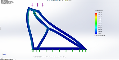
Next, was to decide on a truss pattern. This required a lot of research and testing to accomplish. Firstly, I researched general truss patterns, designed them in Solidworks, and then ran some FEA studies to roughly gauge the behavior of each under a specific load
In the end, I chose a Howe's Truss, as its designed to support compressive loads rather then tensile ones. It also showed the least amount of deformation under the selected load.
FEA Studies of Different
Truss Patterns
Design and Modelling
Once a truss pattern was selected, the next step was to design each individual part needed for the launch tower base, and put it all together in an assembly. These parts include:
-
Pillow Block Bearings and their mounts (used to support a rotating shaft).
-
The trusses themselves.
-
The resting block to achieve a 6 degree angle between the bottom plate and top plate (the height of these blocks was calculated using trigonometry).
-
The bars that are bolted to the top plate to sit on top of the resting blocks.
-
The bottom and top plates with proper holes for bolts.
-
The shaft for the hinge mechanism
After going onsite to grab some dimensions of the already existing parts of the old launch tower base, I was ready to begin CAD modelling each part.
Every part in this assembly, aside from the bolts, were designed by me. Once each part had been designed, I then put everything together in an assembly using a multitude of mates.

Early Stages of Design of the Launch Tower Base

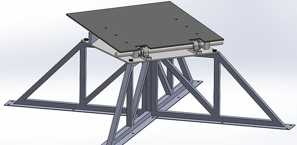
Front and Back of Final Launch Tower Design
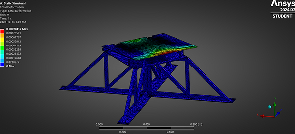
Deformation Study
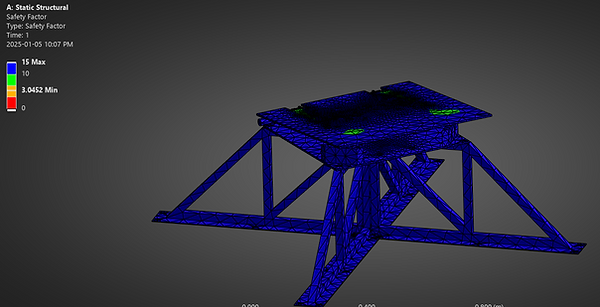
Safety Factor
FEA Simulations
Once the assembly was completed, the last step was to run some simulations to get a rough idea of how the new launch tower will behave under the required load.
Using Ansys Mechanical, I was able to not only run the required simulations, but also utilize an adaptive mesh convergence to increase the accuracy of results. After hours of realizing that Ansys really hates bolts, and threading, I was finally able to achieve results for stress, deformation, and safety factor.
After review, it was decided that manufacturing could commence. (Manufacturing set to be completed by April 2025).

Von-Mises Stress Study
Results
After completing the design, the only thing left was to manufacture the new and improved tower base. The results from this project so far are:
-
Able to support over 8000N of force with less then a mm of deformation.
-
Lightweight and cost effective
-
A safety factor with a minimum of 3.
-
Elevation off the ground so the rocket can be loaded with ease.
-
Using mesh convergence, the error for the study has a maximum of 10%.
-
Personal gratification from Rocketry team leads.
-
Ansys as a technical skill.
